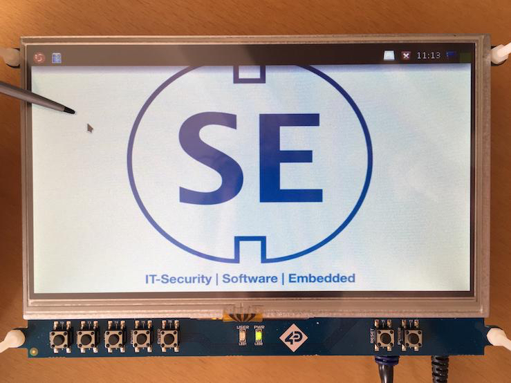
Recently, I bought a 7" touch screen from 4D Systems (4DCAPE-70T) for my Beaglebone Black to use it in a new project. I really like this one, because it is designed as a cape, you just mount the Beaglebone beneath it and that's it. It is automatically recognized by the OS (I prepared the BBB with Debian 9.3) and also the touchscreen is working out of the box. At least, this is what I have thougt. It turned out that the touchscreen calibration is not as easy as expected, not because the "process itself" is complicated, rather the required information is potentially hard to find. This is also the reason why I am writing this down here, it is intended to be a reminder for myself rather than something spectacular.
Basically a touchscreen isn't something complex, but it consists of two independent devices: a transparent touch based input device (nowadays mainly sold as resistive or capacitive) and a display (TFT, LCD, doesn't really matter). Both devices are mounted on each other and therefore need to be synchronised: physically and - let's say - "informationally". This is now where the calibration becomes necessary, because both devices are handled independently by the operating system.
The display shows the widgets in form of pixels, which have a predefined position (a lot of pixels let us then recognise the hole context). The touch based input device works in the opposite direction, it expects a "physical press" somewhere on its surface. The location where the finger (or stylus) caused the "push" is then forwarded to the operating system in form of coordinates (x, y position). If we assume (which is obviously not the case, because we need calibration) that the touch input device and the display are mounted exactly on each other and the coordinates returned by the touch device are congruent to the coordinates used by the system to display the widgets, then we do not need calibration, because we have no offset between both "coordinate systems".
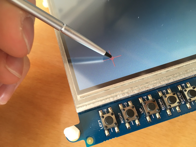
 So now it is clear what the calibration does: It maps two different coordinate systems onto each other and eliminates their offset (as seen in the first picture). This is technically done by showing the user a "point" on the screen and letting him "push" this point with the stylus. By pushing the "point" the system gets a feedback with the "correct" coordinates of the touch device and then maps both coordinate systems.
As described, the user just has to do some clicks on the screen and the system takes care for adapting the calibration matrix. A tool which is often used for this is called xinput_calibrator. One reason, I (and also others) could not walk through this toppic as intended, was the fact that in modern Linux systems the touchscreen calibration is not handled by xorg.confs anymore. When running xinput_calibrator it is returning the calibration values in a xorg.confs compatible format, which cannot be used anymore. Instead, the calibration matrix has to be determined manually. Anyhow, xinput_calibrator is still a helpful tool for that, the calibration data will later be set using the xinput command (https://github.com/tias/xinput_calibrator). The proceeding can be described as follows:
- Check available input sources, identify the touchscreen and check its properties:
debian@beaglebone:~$ xinput list
⎡ Virtual core pointer id=2 [master pointer (3)]
⎜ ↳ Virtual core XTEST pointer id=4 [slave pointer (2)]
⎜ ↳ ti-tsc id=6 [slave pointer (2)]
⎣ Virtual core keyboard id=3 [master keyboard (2)]
↳ Virtual core XTEST keyboard id=5 [slave keyboard (3)]
↳ gpio_keys id=7 [slave keyboard (3)]
↳ tps65217_pwr_but id=8 [slave keyboard (3)]
- Check the device-properties, especiall look for "libinput Calibration Matrix":
debian@beaglebone:~$ xinput list-props "ti-tsc"
Device 'ti-tsc':
Device Enabled (116): 1
Coordinate Transformation Matrix (117): 1.0, 0.0, 0.0, 0.0, 1.0, 0.0, 0.0, 0.0, 1.0
libinput Calibration Matrix (379): 1.00, 0.0, 0.0, 0.0, 1.0, 0.0, 0.0, 0.0, 1.0
libinput Calibration Matrix Default (380): 1.0, 0.0, 0.0, 0.0, 1.0, 0.0, 0.0, 0.0, 1.0
libinput Send Events Modes Available (381): 1, 0
libinput Send Events Mode Enabled (382): 0, 0
libinput Send Events Mode Enabled Default (383): 0, 0
Device Node (384): "/dev/input/event0"
Device Product ID (385): 0, 0
- Now we can run
xinput_calibrator -vto get the verbose output --> x and y coordinates. The outputs can be ignored except for those which are marked as debug outputs:
DEBUG: Adding click 0 (X=107, Y=64)
DEBUG: Adding click 1 (X=698, Y=61)
DEBUG: Adding click 2 (X=104, Y=420)
DEBUG: Adding click 3 (X=704, Y=420)
- Now we run xrandr to get the current display settings, important is the resolution which is shown under "current":
Screen 0: minimum 800 x 480, current 800 x 480, maximum 800 x 480
- This is important for the following calculation, which needs to be done by hand (in this case):
a = (screen_width * 6 / 8) / (click_3_X - click_0_X)
c = ((screen_width / 8) - (a * click_0_X)) / screen_width
e = (screen_height * 6 / 8) / (click_3_Y - click_0_Y)
f = ((screen_height / 8) - (e * click_0_Y)) / screen_height
I have found these formula in a discussion thread at https://wiki.archlinux.org/index.php/Talk:Calibrating_Touchscreen :Calibrating_Touchscreen, it describes the 3x3 transformation matrix to determine the absolute device coordinates, which are used to set the calibration parameters. The 3x3 transformation matrix is defined in the libinput source documentation.
- in my case it looks like this now:
a = (800 * 6 / 8) / (681 - 112) = 1.05448
c = ((800 / 8) - (a * 112)) / 800 = -0.02262
e = (480 * 6 / 8) / (406 - 89) = 1.13564
f = ((480 / 8) - (e * 89)) / 480 = -0.08556
- That's basically all to do for the calibration. To activate the calibration using xinput the values will be placed like this:
xinput set-prop "ti-tsc" "libinput Calibration Matrix" a, 0.0 c, 0.0, e, f, 0.0, 0.0, 1.0
xinput set-prop "ti-tsc" "libinput Calibration Matrix" 1.05448, 0.0 -0.02262, 0.0, 1.13564, -0.08556, 0.0, 0.0, 1.0
- Depending on the operating system and configuration, you can place the command either in
~/.profileor in~/.xsessionrcor somewhere else, just ensure that the file is sourced automatically after boot.